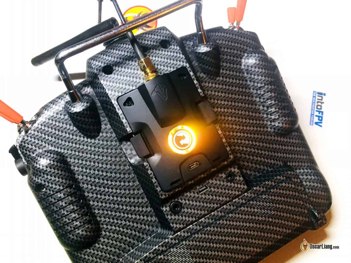
This guide provides instructions on configuring TBS Crossfire for OpenTX transmitters like the TX16S. Additionally, it will demonstrate the process of linking the Crossfire receiver to a flight controller and setting it up in Betaflight. The setup process for Tracer is quite similar to that of Crossfire, so many of the steps outlined here will be relevant for Tracer as well.

Certain links on this page are affiliate links. If you make a purchase by clicking on one of these links, I earn a commission at no additional cost to you. This supports the free content available to the community on this site. For further details, please refer to our Affiliate Link Policy.
Contents
What is TBS Crossfire?
Contents
- 1 What is TBS Crossfire?
- 2 Upgrading EdgeTX
- 3 Upgrading the TBS Crossfire Firmware
- 4 Integrating the Crossfire TX module into the radio system.
- 5 Configure the radio to activate the Crossfire TX module.
- 6 RX and FC Link
- 7 Binding Crossfire Transmitter
- 8 Setting up RX via Radio
- 9 Set up Betaflight for Crossfire.
- 10 Telemetry
- 11 Installing the Crossfire Receiver Antenna
- 12 LQ and Received Signal Strength Indicator (RSSI)
- 13 What is the maximum number of individuals allowed to fly on Crossfire?
TBS Crossfire is a widely used radio control system for FPV drones, recognized for its dependability, straightforward setup, and excellent performance in long-range flights.
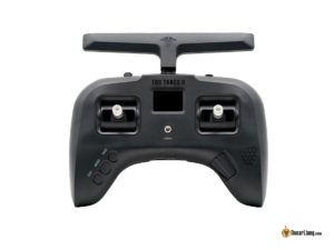
Crossfire is an external RF module designed for direct installation on the rear of a radio transmitter, such as the JR module bay. Additionally, the TBS Tango 2 radio features an integrated Crossfire system.
Instead of utilizing the more prevalent 2.4GHz frequency, Crossfire functions on the 900MHz band. This lower frequency allows for improved signal penetration through various obstacles. Many pilots choose Crossfire, even if they don’t plan on flying long distances, due to its reliable link connection and its ability to resist failsafe issues in difficult environments. The range can vary significantly based on environmental factors, but in my experience, I can easily fly 5 miles using 250mW, and I wasn’t even testing the limits. One of the notable drawbacks of Crossfire is the larger receiver antennas, which can pose difficulties when trying to mount them on smaller FPV drones.
Crossfire TX Units
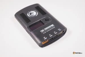
| TBS Crossfire TX Module | TBS Crossfire Micro TX V2 |
 |
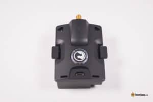 |
| – Built-in screen for changing settings – Max Power up to 2W – Extra features: Spectrum analyzer, Bluetooth module | – More practical and greater value – No screen, settings changed via LUA script only – Max Power up to 1W (1000mW) – Lighter, smaller, cheaper |
| AliExpress Amazon NBD | GetFPV NBD Amazon |
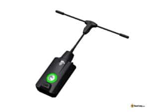
In my opinion, the Micro V2 module is sufficient for the majority of individuals engaged in freestyle flying and racing. The integrated display in the full-size module isn’t particularly significant, as nearly all settings can be adjusted directly on the radio. To be frank, the extra features of the full-size module aren’t particularly beneficial for most pilots. The only real benefit, in my view, is the option for 2W output power, and I can’t recall ever needing more than 250mW.
TX Antenna Systems
| Stock Antenna | Diamond Antenna (Upgrade) |
 |
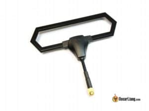 |
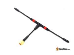
| – Good enough for most pilots – Durable, Cheap – Can be used for receiver | – Slightly more reliable performance – Slightly more directional, more range in front of the pilot than behind – Durable design for transport |
| AmazonAliExpress | GetFPVAmazon |
Receivers
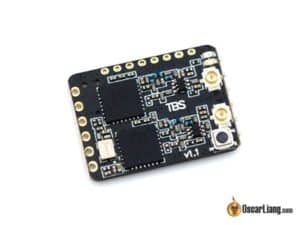
| Crossfire Micro RX | Crossfire Nano RX |
 |
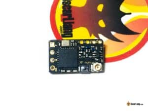 |
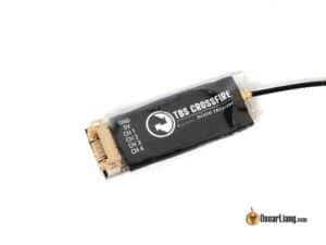
| It uses a JST header for connection | Same capability as the Micro RX, but a lot smaller! Connection is solder pads |
| AmazonGetFPV | GetFPVAmazonNBD |
RX Antenna Systems
Upgrading EdgeTX
Prior to initiating the setup of Crossfire, it’s advisable to verify that the operating system of your radio, such as OpenTX or EdgeTX, is current to benefit from the latest bug fixes and enhancements.
- Steps to upgrade OpenTX.
- Steps to upgrade EdgeTX
Ensure that you refresh the contents of the SD card, as it includes the most recent Crossfire LUA script for setting up the Crossfire module and receivers.
Upgrading the TBS Crossfire Firmware
The initial step you need to take is to upgrade the firmware on your Crossfire TX module to access the newest features and resolve any existing issues.
In the past, prior to 2020, it was necessary to download and install the TBS Agent software on our computers. However, we now have the convenience of a web-based tool to flash the firmware on our Crossfire module, making the process much easier.
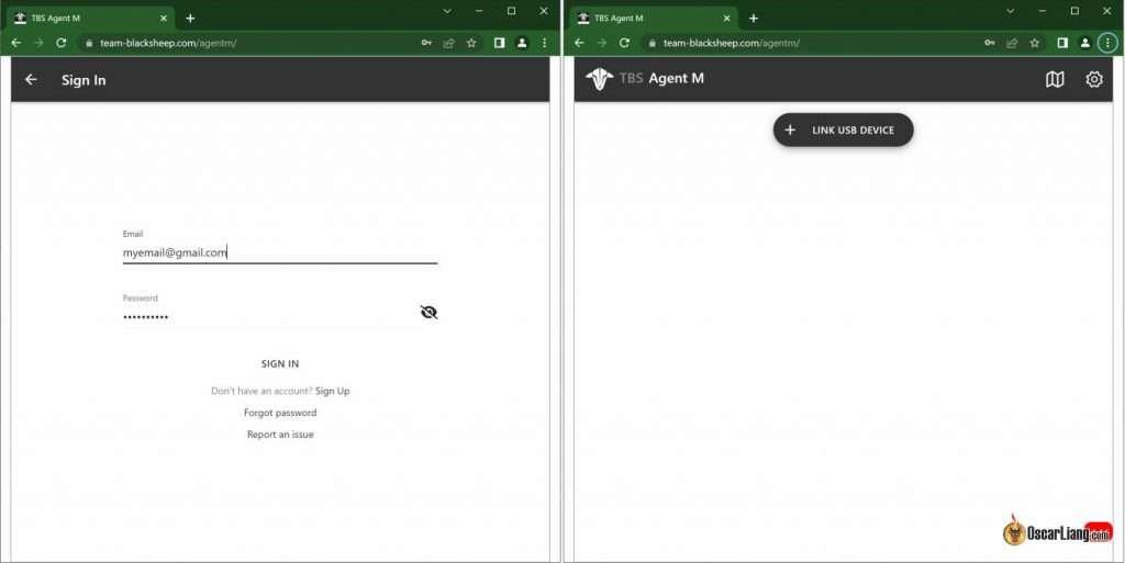
The web-based application known as AgentM can be found at this link: https://www.team-blacksheep.com/agentm/. Please be aware that it currently only functions with Google Chrome and Microsoft Edge browsers.
Sign in using the same account you utilize on the TBS website, with your email address as the username. If you haven’t created an account yet, you can easily register on TBS’s website (https://www.team-blacksheep.com).
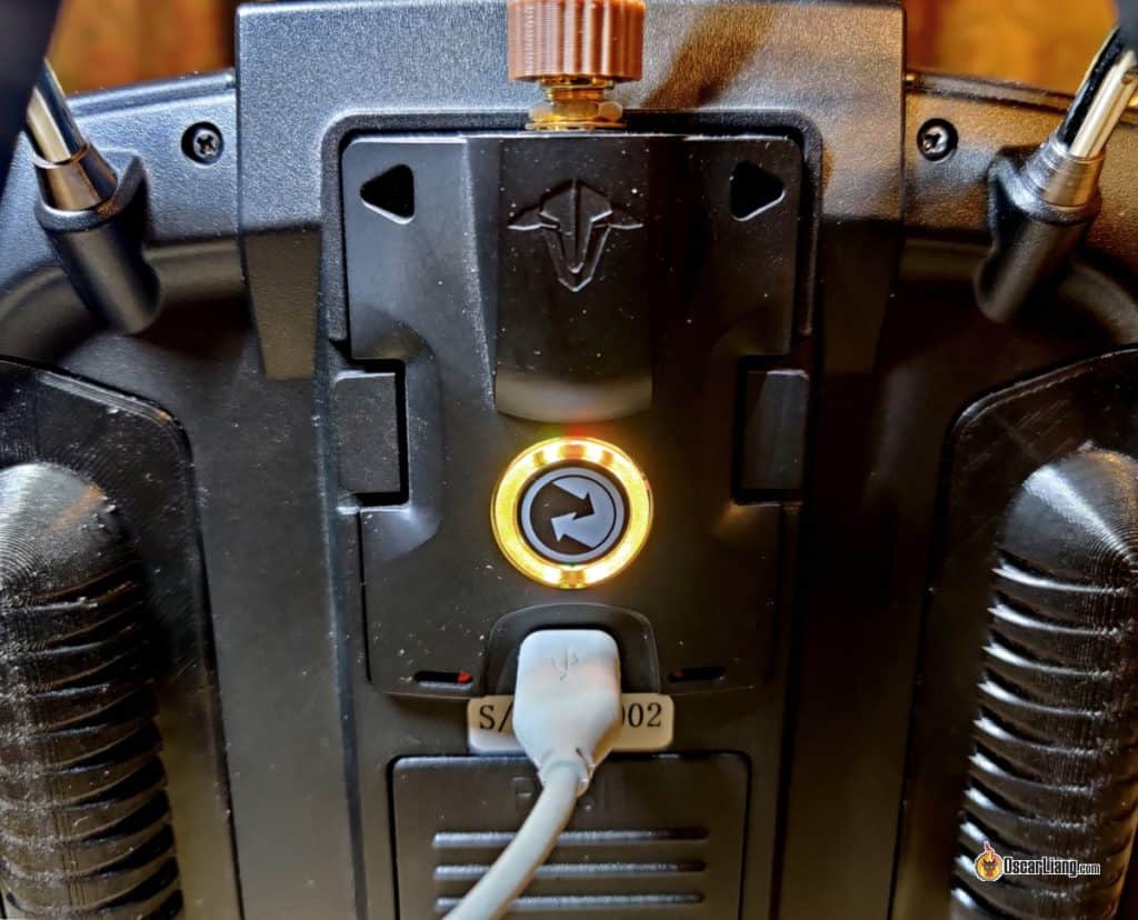
Link your Crossfire TX module to your computer via a USB cable. There’s no requirement to turn on your radio for this to function, as the module receives power directly from the USB connection.
In Agent M, select the option to “link USB device,” and you will receive a prompt to establish a connection with TBS Crossfire.
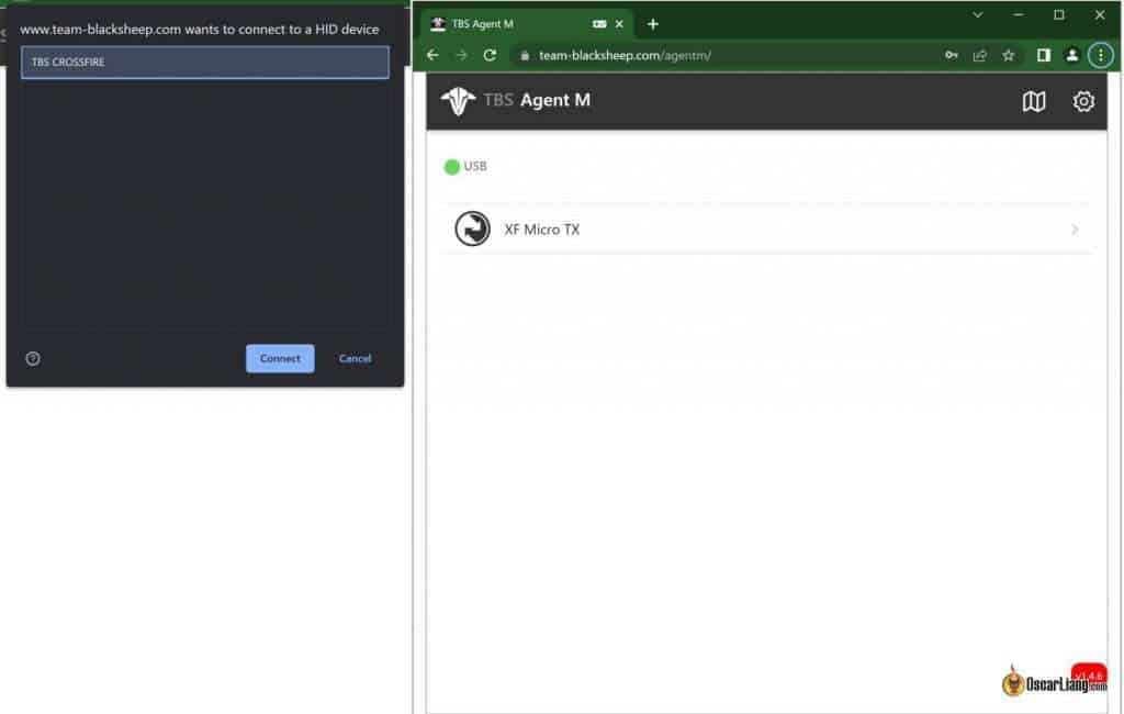
After establishing a connection, you will be directed to a new page that allows you to set up the Crossfire TX module.
To refresh the firmware, press the “Firmware” button located at the bottom. A list of available firmware updates will appear. The firmware version you are currently using will be indicated by a blue label stating “Current.”
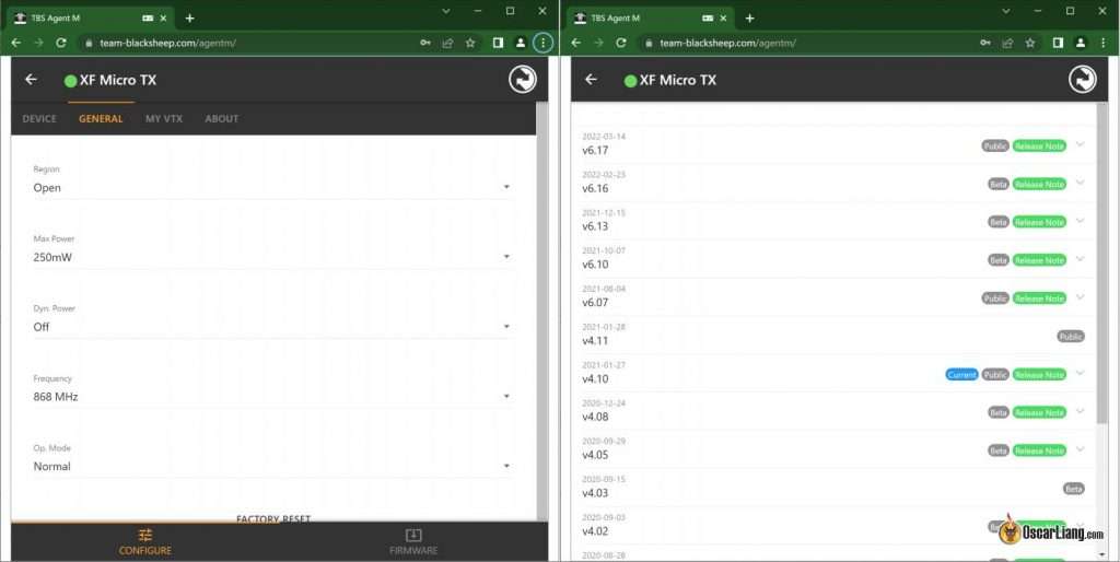
The update is expected to finish in just a minute or two.
Whenever you upgrade the firmware on your TX module, it’s essential to also upgrade the firmware on your receivers. The process is straightforward: simply turn on your radio and your quad, attempt to bind them once more, and you should receive a prompt to wirelessly update the firmware on the receiver.
Integrating the Crossfire TX module into the radio system.
The Crossfire TX module can be directly installed in the external JR module bay located at the rear of the radio. Carefully insert the module, ensuring that all the pins fit securely into the sockets of the Crossfire module.
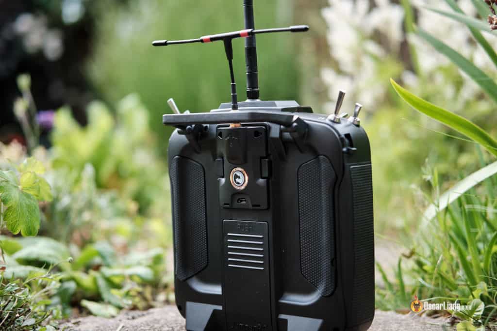
The Crossfire module works seamlessly with radios that feature a JR module bay, including models like the Frsky Taranis X9D+, Jumper T18, T16, RadioMaster TX16S, and Radiomaster Boxer.
It is compatible with Taranis Q X7 and Horus X10S, but users may encounter some minor issues because these transmitters cannot function at the maximum baud rate, leading to persistent alerts of “telemetry lost.” While there is a DIY modification available to resolve this, it is quite challenging, as it requires soldering to the main processor, so I would advise against using these transmitters with Crossfire. However, an update indicates that by installing EdgeTX on these radios, the hardware modification is no longer necessary.
Configure the radio to activate the Crossfire TX module.
You will need to develop a new model in the radio specifically for Crossfire. One straightforward approach is to copy an existing model and change its name to “Crossfire.” Alternatively, if you prefer to build it from the ground up, you can follow this tutorial for guidance.
Quickly press the Menu button to access the Model Setup page, then scroll down to “Internal RF” and change the mode to “OFF.”
Then, adjust the mode in the “External RF” section to “CRSF” and modify the “Channel Range” to “CH1-16.”
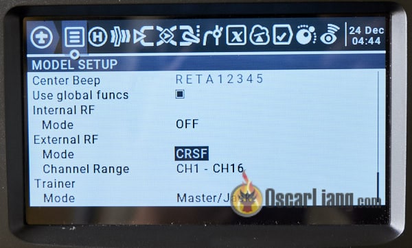
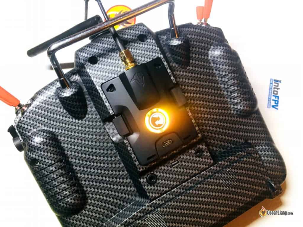
After completing this step and leaving the menu, the Crossfire TX module should activate, indicated by the LED lighting up on the back.
RX and FC Link
Keep in mind that nearly all the pins on the Crossfire receiver can be programmed through software. This allows you to set them up to produce the desired output, providing multiple options for linking your receiver to the flight controller.
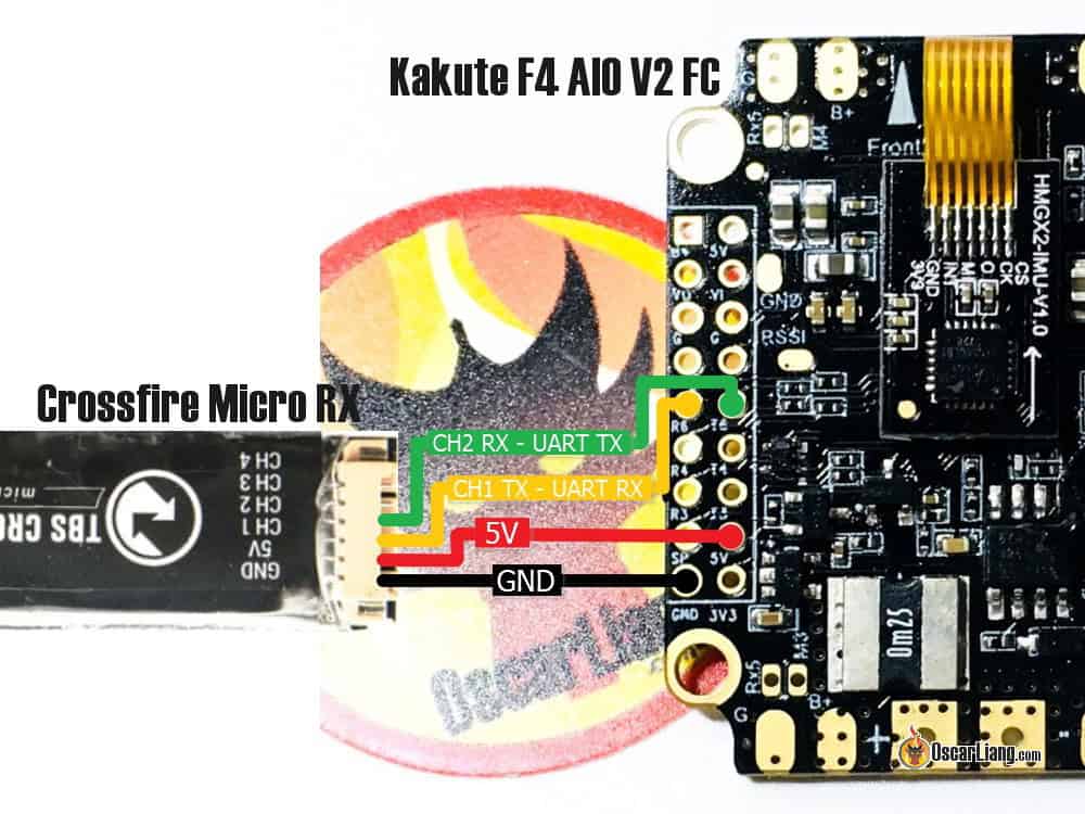
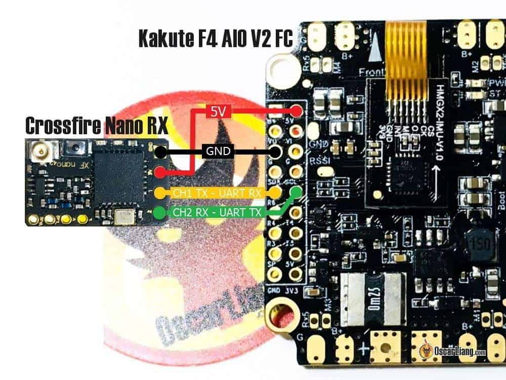
The method I’m presenting is a common approach utilized by many, and here are the connections:
Any available UART on the flight controller can be utilized.
Guide: Configuring Crossfire to transmit SBUS instead of CRSF
The Crossfire receiver can be set up to output SBUS, enabling you to connect just CH1 to an RX pin on the flight controller while leaving CH2 disconnected. This is particularly beneficial if the flight controller lacks a TX pin. However, CRSF is a superior protocol compared to SBUS, as it offers faster communication and supports telemetry, which is why I would suggest using it.
Using Soft Serial for a Crossfire receiver is not advisable, as it lacks the speed required to effectively manage the CRSF signal.
In this instance, I am linking the Crossfire receiver to the UART 6 port on the Kakute F4 AIO V2 flight controller.
Crossfire Mini Receiver:
Crossfire Nano Transmitter:
Binding Crossfire Transmitter
Binding the Crossfire receiver is usually a straightforward process. You can enable the binding mode through the Crossfire LUA script, which is included with the latest versions of EdgeTX and OpenTX, eliminating the need for any additional downloads.
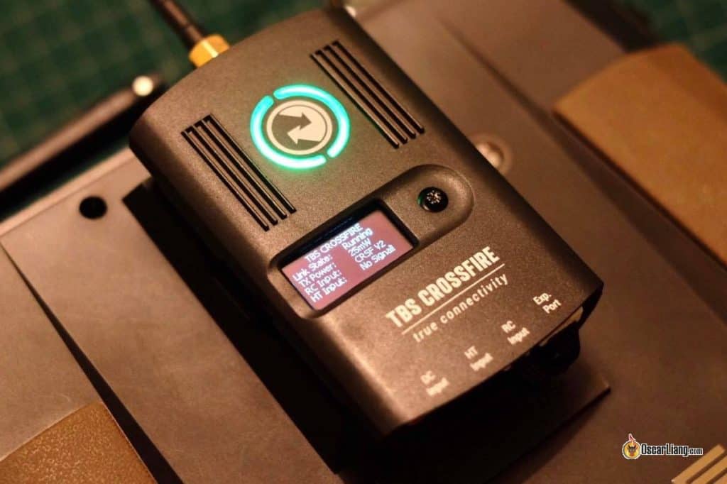
TBS Crossfire “Full” Module Mounted on the Rear of the Horus X10
Below are the instructions for pairing the Crossfire TX module with the RX:
- Turn on the RX; the LED should blink green, signaling that it is in binding mode. If the LED remains red, press the bind button on the RX, and it should begin to flash green.
- Switch on your radio and press and hold the System button to access the Radio Setup.
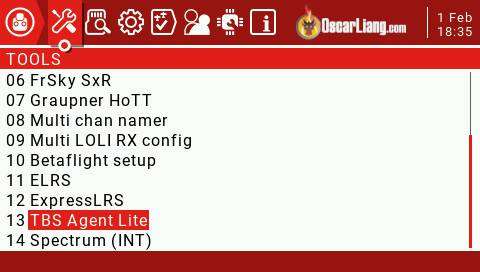
- On the “Tools” section, choose “TBS Agent Lite.”
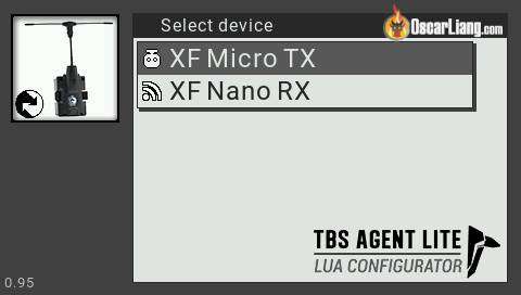
On the following screen, choose “XF Micro TX” (which is your transmission module).
On the following screen, choose the second option labeled “Bind.”
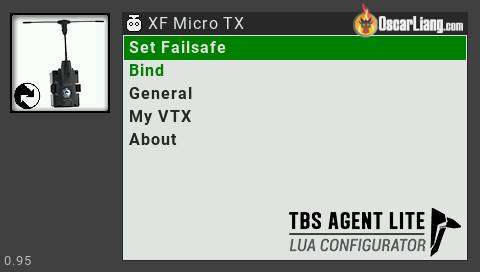
You will see a message that says “Binding…”, and this process should only take a few moments to complete.
If the RX is running an older version of the firmware, you will receive a notification to perform an update, which will take a few minutes to complete. After the update is finished, the receiver will blink green quickly for a few seconds (indicating firmware loading), and then the green lights on both the RX and TX modules will remain steady. In case the update is interrupted or fails, simply attempt the process again.

Once the binding process is finished, the radio will automatically leave binding mode, and the receiver’s LED will change from red to a steady green.
Press the exit button on your radio to set up the Crossfire Nano receiver.
Setting up RX via Radio
After binding your receiver, you can set up both the TBS Crossfire TX module and the receiver using the Crossfire Configure Tool on your radio. If the “XF Micro/Nano RX” option is not visible, it indicates that your receiver is either unbound or turned off.

The initial step in the setup process is to configure the output mapping of your receiver to establish communication with your flight controller.
To accomplish this, choose “XF Nano RX,” then scroll down to “Output Map” and modify “Output 1” to “CRSF TX” and “Output 2” to “CRSF RX.” That’s all there is to it! 🙂

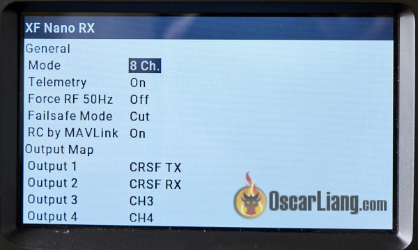
You can now set up the TX module.
Region
Setting the “Region” option to “Open” enables the highest output power, no matter the frequency you choose.
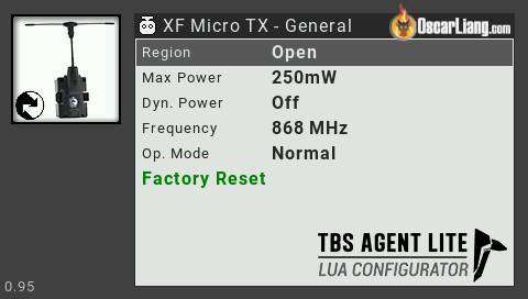
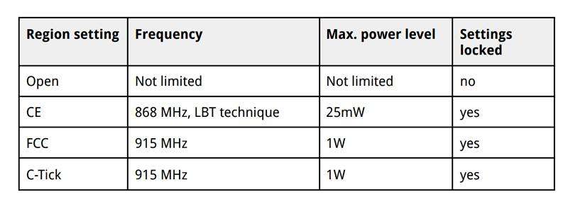
Source: Crossfire Guide
Frequency
Ensuring that you select the appropriate frequency is crucial based on your flying location. You have two choices: 868MHz and 915MHz. One of these frequencies is utilized by the cellular network, and it’s best to steer clear of that frequency to prevent interference, which could lead to disruptions and failsafe activations.
The Crossfire manual specifies that the Blue and Purple areas are to operate on 915MHz, whereas the Yellow area is designated for 868MHz. For instance, the United States is expected to utilize 915MHz, while Europe is to operate on 868MHz.
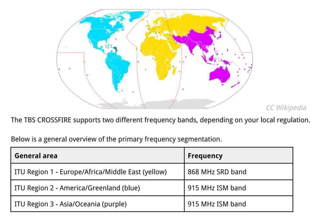
Source: Crossfire Guide
Here are the various frequency choices available. Utilize the Race frequencies solely when participating in a race, as they prioritize bandwidth over range to ensure more reliable data transmission. LBT stands for “listen before talk.”
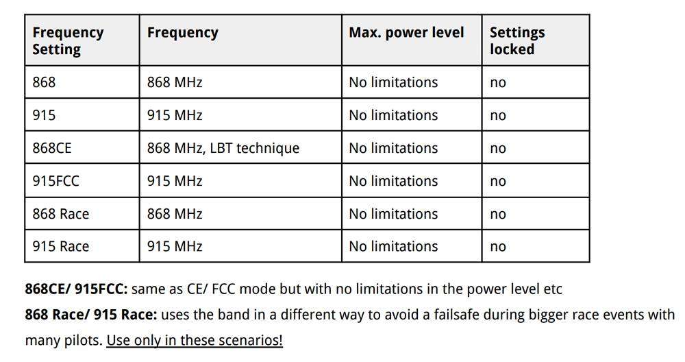
Region and frequency information for Tracer is not provided, as it operates on the 2.4GHz frequency, which is the same globally.
Ultimate Strength
Increased output power translates to a greater range, but it’s not always necessary to operate at maximum power levels.
To begin with, increased output power leads to quicker battery depletion. Additionally, when flying with others—particularly if everyone is utilizing Crossfire or other 900MHz systems—there is a risk of interference, which can result in signal loss and failsafe activation if everyone is operating at maximum power. For short-range scenarios, like racing, opting for 25mW is likely a wise choice.
In a standard FPV drone configuration, a power setting of approximately 250mW is usually sufficient, allowing for several miles of range when flying within visual range.
Dynamic Power
The option for dynamic output power can alleviate several issues associated with maximum output power. It automatically modifies the output power based on the strength of the signal. However, be cautious, as unplugging the quad will cause the transmitter to revert to maximum output power, which can be problematic when flying in the vicinity of others using Crossfire.
In Tracer, you can choose from power levels of 25mW, 100mW, and Ludicrous, which is approximately 1W. Since Tracer has a shorter range compared to Crossfire, many users opt to use Ludicrous mode with Dynamic power activated, allowing the power to decrease when flying in close proximity.
Receiving Mode
Another setting you should adjust is the “Mode” in the Receiver settings. Access to the receiver options is available only when the receiver is connected to the transmitter and turned on. Keep in mind that these settings are saved individually for each receiver, so you will need to configure them for each quad you own.
The mode refers to the number of channels you wish to utilize, with two available choices: 8 channels or 12 channels.
Simply choose 12 channels.
You will gain access to four additional channels. While you might not find them necessary, the performance between the 8Ch and 12Ch modes is essentially the same. Those extra four channels will prove useful when the need arises.
For fixed-wing aircraft, if you desire maximum resolution across all channels, it’s best to stick with 8 channels. In contrast, using 12 channels is acceptable for multirotors.
Ensure that telemetry is activated and configure the Failsafe to Cut, which will halt the motors if the signal is lost, causing your quad to descend safely to reduce potential damage.
RF Profile
You have the option to choose your desired packet rate, with available settings of 50Hz, 150Hz, or Dynamic.
The choice between lower latency and extended range is crucial. A frequency of 50Hz offers greater range due to its enhanced receiver sensitivity and the use of LORA modulation, although it comes with increased latency. In contrast, 150Hz provides reduced latency but at the cost of range.
You have the option to configure it to dynamic mode, which will automatically adjust to a lower latency when your signal weakens. Nevertheless, the Betaflight developers advise against using the dynamic setting because the RC signal smoothing in the flight controller firmware is linked to a constant packet rate, which may not function correctly with a variable packet rate. For long-range flying, it is best to set it to 50Hz, while 150Hz is suitable for racing or flying in close proximity.
Set up Betaflight for Crossfire.
The final stage of configuring our software involves activating the Crossfire protocol within Betaflight.
Navigate to the “Ports” section in the Betaflight configurator and activate “Serial RX” for the UART that is connected to the TBS Crossfire receiver. Then, click “Save.”
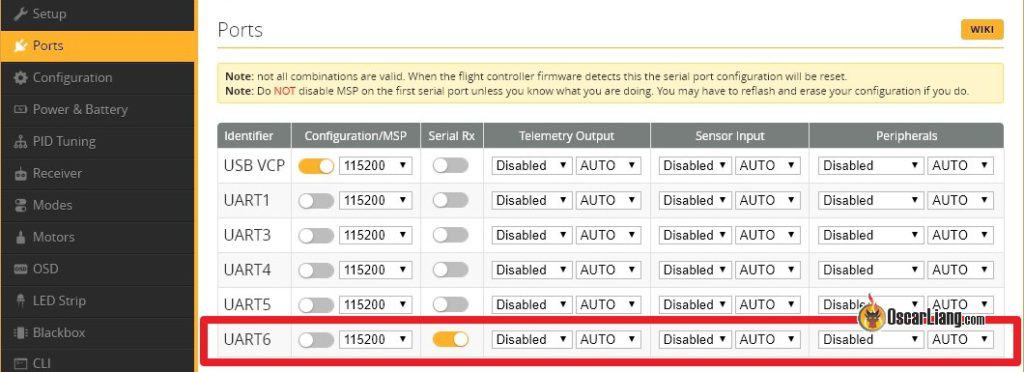
Next, navigate to the “Receiver” tab. In the “Receiver” section, choose “Serial (via UART)” and then select “CRSF” from the second option. Make sure to activate “Telemetry” as well before clicking “Save.”
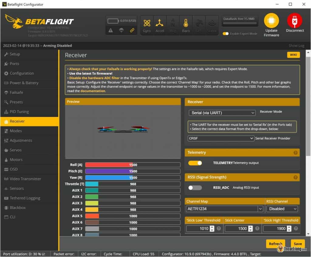
Congratulations, you’ve successfully configured Crossfire in Betaflight!
Return to the “Receiver” tab, and you should now observe the response from the stick movement. This indicates that your receiver is functioning properly! If the channels are not arranged correctly, simply select a different “Channel Map.”
Verify whether the endpoints (1000 and 2000) and the midpoint (1500) are accurate. Refer to this guide for instructions on how to make adjustments if they are not.
If your stick isn’t responding, you can use this command in the command line interface: set serialrx_inverted = OFF.
If you’re still experiencing a lack of stick response, revisit your wiring, the Output Map settings in the receiver, and your Betaflight configurations. If the issue persists, consider seeking assistance at IntoFPV.com!
Telemetry
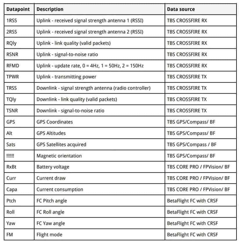
To verify that Telemetry is functioning properly, navigate to the Telemetry section on the radio and choose the “Discover new sensors” option. This will initiate the process of gathering data from the flight controller, which includes the RxBt (drone battery voltage).
Below is a compilation of the accessible Crossfire Telemetry data along with their respective meanings. Some of the commonly utilized data points include: RxBt, which indicates battery voltage; RQly, representing link quality; and RFMD, denoting the update rate.
Installing the Crossfire Receiver Antenna
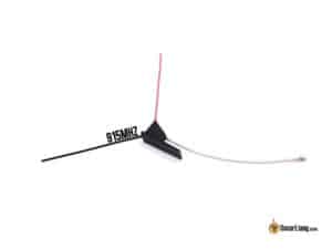
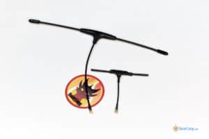
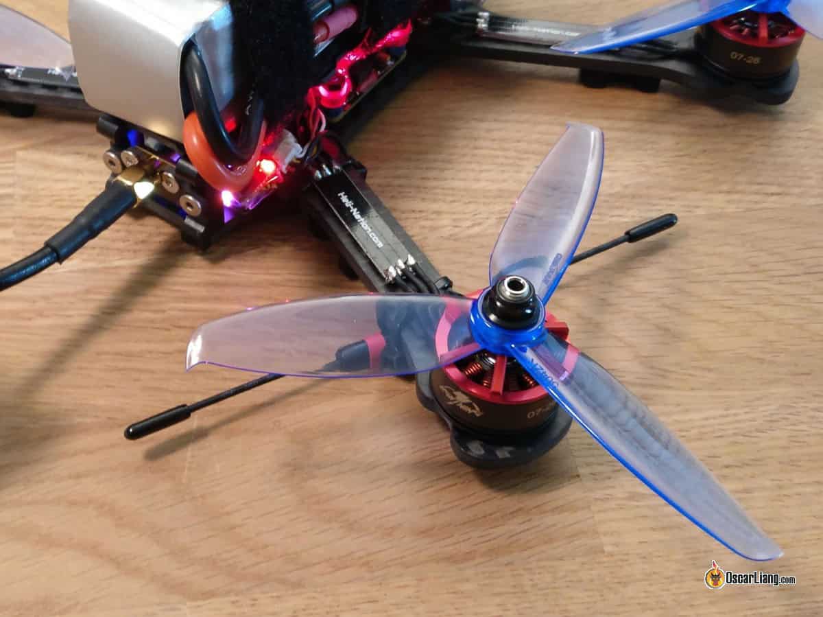
If you’ve previously utilized different radio systems, the initial challenge you’ll encounter is the installation of the notably large receiver antenna. Explore the various methods for mounting the Crossfire antenna and the impact each method has.
LQ and Received Signal Strength Indicator (RSSI)
LQ and RSSI are two key indicators of the quality of your radio signal. I have created a comprehensive guide on interpreting LQ and RSSI within the Crossfire system. Additionally, this guide will cover how to show these metrics on your Betaflight OSD and how to configure voice alerts on your transmitter.
What is the maximum number of individuals allowed to fly on Crossfire?
As reported by TBS, in theory, Crossfire can accommodate simultaneous flights for as many as 50 individuals. However, practical tests indicate that when 12 users are in the air concurrently, the quality of the radio connection significantly deteriorates, although it remains operational. Therefore, TBS advises against exceeding that number for simultaneous flights. 🙂
Revision Log
- March 2018 – Guide developed
- January 2019 – Revised product links and configuration information.
- December 2019 – Included screenshots for the Jumper T16.
- In June 2020, the latest version of Agent X was released, the Crossfire LUA script was relocated to the Tools section in OpenTX, and the Micro TX V2 was introduced.
- February 2023 – Revised guidelines and updated product links.
earlier post
How to Link or Flash Flight Controller to Betaflight When the USB Port is Damaged?
Review: Caddx Walnut HD Action Camera – An Affordable Option for FPV Drones
Post a CommentWithdraw Response
83 responses
Greetings, July 17, 2024 – 6:11 AM.
Hello, I would greatly appreciate any insights regarding the issue described below. The issue is that Betaflight is not receiving any data from the receiver, resulting in blank receiver tabs. A friend and I purchased a Crossfire module for our Zorro; I have a diversity receiver, while he has a Pro and a normal receiver. The wiring is correct (TX to RX) with no shorts, and we are using the latest official version from 2022, avoiding any beta versions. The binding process is successful, with a constant green light. In Betaflight, I have selected the correct UART. To troubleshoot, I also attempted to solder to different available ports, but the result remains unchanged. In Betaflight, we have selected serial with CRSF, but we still see no data from the receiver, and the receiver tabs are completely blank, with no options to select telemetry or RX failsafe.
Alex, June 24, 2024 – 8:18 PM
Hello everyone. Does anyone have details about the JR pinout for CRSF? The pin at the bottom appears to be sending a signal that varies with stick movements, but the CRSF Arduino library doesn’t seem to detect it, whereas the output from the ELRS/TBS receiver picks it up without issues. I’m currently using a single signal wire, akin to SBUS, and have not implemented telemetry yet. Is it possible that the CRSF from the ELRS receiver and the CRSF from the JR Bay are not the same?
Moav Winnykamien, June 6, 2024, at 12:41 PM.
Can anyone provide information on the pin configuration for the Nano module? I need to create a custom cable to connect the module to my Jumper T20 bay.
Seii, March 14, 2024, at 4:32 PM.
Hello Oscar, I have a question about the “Discover new sensors” process, and I couldn’t find any information online. How frequently do we need to discover new sensors? Is it a one-time process, or do we need to do it again before each flight? If we discover sensors once, will they still be recognized the next time we arm the quad, whether it’s the next day or a week later? I use CRSF on some of my custom-built quads and ELRS on the others.
Oscar, March 15, 2024 – 9:11 PMYou should only perform this action when sensors or telemetry are absent.Seii, March 16, 2024 – 5:58 AM
I really appreciate it! Everything is much more understandable now. Thank you for all the hard work you’re dedicating to this. You are among the few who form the strong foundation of FPV. Many are gaining knowledge from the incredibly valuable insights you generously share. Thank you!
LuVi FPV, October 22, 2023 – 7:29 PM
Hello Oscar, great guide! Thank you. I’ve been using Crossfire for three years with a Taranis x9d+2019, but after the TBS update and the upgrade to Betaflight 4.4, I’m experiencing a serious power issue. I’ve set the micro to 1W power and not dynamic. However, at 2 km, the drone starts to lose signal signif


